
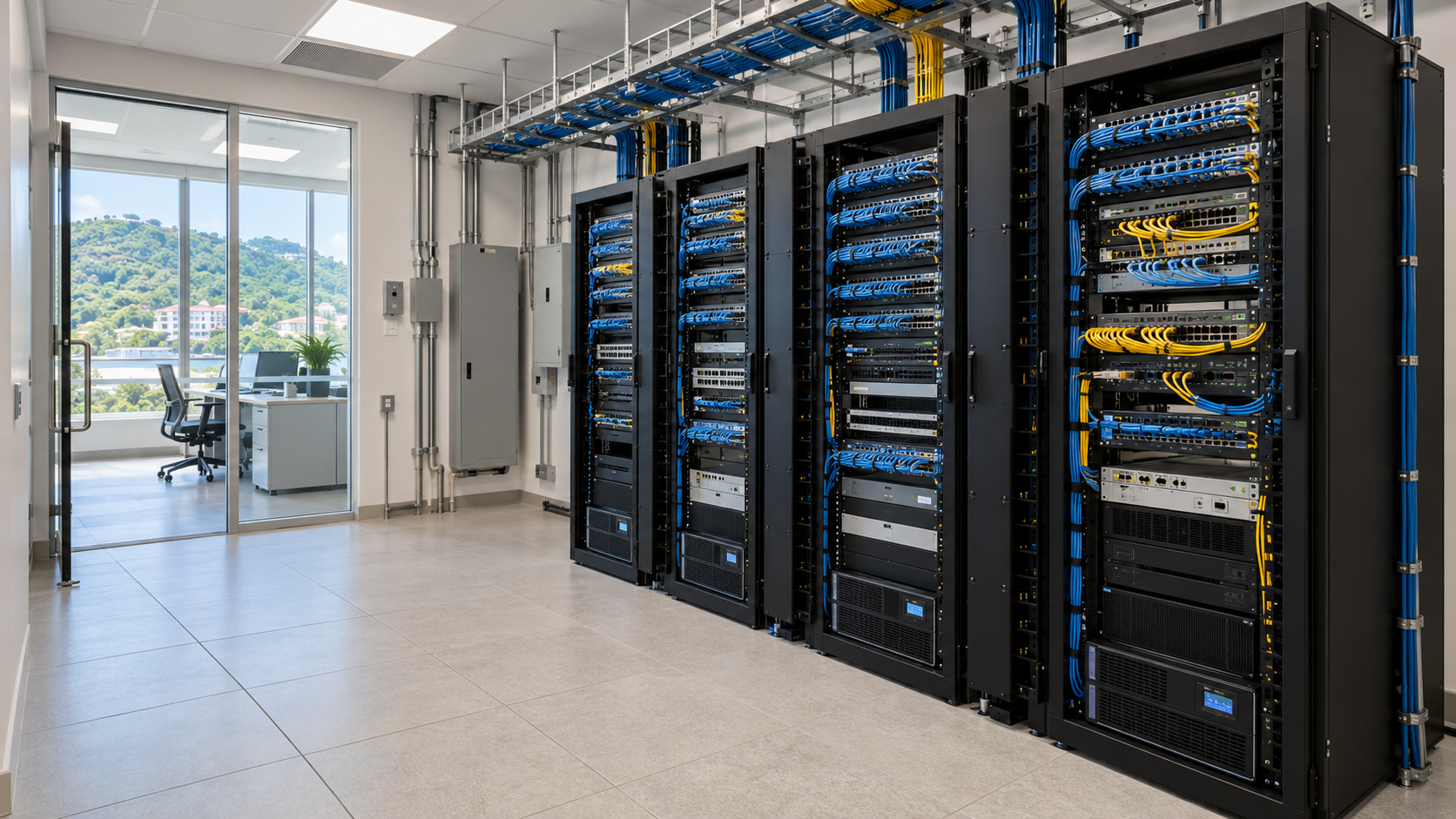
Communications-room infrastructure / British Virgin Islands
Data Center, MDF & IDF Infrastructure Design and Installation
More than a rack. A coordinated infrastructure room built around the systems, people and operations it supports. MicroAntix brings room planning, backbone cabling, equipment layout and commissioning together for demanding business environments.
A complete physical foundation
The room is a system.
Design it as one.
Rack installation provides an enclosure. Server-room cleanup improves an existing arrangement. A complete MDF, IDF or data-center infrastructure project connects those decisions to the room’s role, backbone routes, equipment capacity, utility dependencies and documented operating requirements.
We work with your IT team, property representatives, consultants and specialist contractors to define responsibilities before installation. The aim is an environment that can be accessed, traced, tested and expanded without relying on undocumented knowledge.
The building’s central connection.
Core network and service handoffs, backbone termination, primary patching and distribution to supporting rooms.
Infrastructure closer to users.
Floor, wing or building distribution aligned with cable routes, endpoint demand and maintainable equipment access.
Capacity with coordinated dependencies.
Rack and cabling infrastructure for IT equipment, with electrical, cooling, security and facilities interfaces defined in the project scope.
From the room plan to acceptance
Nine connected disciplines.
One coordinated delivery.
Explore what is included in a complete communications-room engagement. Every installation is scoped around the property, the equipment and agreed acceptance criteria.
01 / Architecture & capacity
Plan the room
Defined requirements and accountable handoffs.
Main Distribution Frame (MDF) design and deployment
We define the primary communications-room role, incoming service handoffs, core connectivity and distribution requirements. Room layout considers rack positions, service access, cable entry points, growth and the operational needs of the building or campus.
Project deliverablesSite survey, MDF arrangement, equipment schedule, backbone topology and documented interfaces to the wider project team.
Intermediate Distribution Frame (IDF) installations
IDFs are planned around the areas they serve, available pathways, cable distances, equipment demand and practical maintenance access. We coordinate the connection back to the MDF and the distribution onward to work areas, guest rooms or specialist systems.
Project deliverablesIDF location and capacity review, cabinet layout, termination schedule and installation aligned with the agreed building design.
Network cabinet and rack elevations
A rack elevation is a working plan, not simply a list of devices. We position patch panels, switches, servers, cable managers and power distribution around equipment dimensions, loading information, airflow and access requirements.
Project deliverablesNumbered rack-unit layouts, equipment allocation, patching zones, reserved capacity and manufacturer installation requirements.
02 / Backbones & distribution
Build the pathways
Defined requirements and accountable handoffs.
Fiber and copper backbone systems
We select backbone media and termination arrangements for the distances, applications and capacity required. Existing links are assessed before reuse, and optical compatibility, copper channel requirements and segregation are considered in the design.
Project deliverablesCable and fiber schedules, route plans, termination details, splice records where applicable and documented link test results.
Overhead cable trays and ladder racks
Overhead distribution keeps routes visible and serviceable when planned correctly. We coordinate tray and ladder-rack positions with room access, cable support, bend-radius requirements and the building’s other services.
Project deliverablesPathway layout, cable routing and fill planning, fixing coordination and confirmation of specialist structural or fire-stopping requirements.
Structured patching and equipment layout
Consistent patching makes changes easier to trace and reduces avoidable disruption. We organize fiber and copper patch fields, allocate equipment ports and provide manageable cable lengths and routing for day-to-day support.
Project deliverablesPort-to-port schedules, a consistent labeling scheme, cable management, equipment placement and a clear handover baseline.
03 / Utilities & acceptance
Coordinate & commission
Defined requirements and accountable handoffs.
Grounding and bonding coordination
We identify the communications infrastructure that needs to be coordinated with the building’s earthing and bonding design. Interfaces are reviewed with appropriately qualified electrical professionals before installation.
Project deliverablesAn agreed responsibility matrix and bonding requirements for relevant racks, cabinets and metallic pathways. Regulated electrical work is performed and verified by qualified professionals.
Equipment power, UPS and cooling coordination
Equipment schedules inform the required power, UPS capacity, heat-load review and maintenance arrangements. We coordinate IT requirements with electrical and mechanical specialists, including approved shutdown, resilience and service-access requirements.
Project deliverablesDocumented equipment loads, UPS and distribution requirements, cooling inputs and utility dependencies. Electrical circuits, protective devices and HVAC work remain within the qualified specialists’ scope.
Full labeling, testing and commissioning
The room is handed over against agreed acceptance criteria. We check identifiers, physical installation, patching records and cabling performance, then coordinate functional checks with the active-equipment and facilities teams.
Project deliverablesLabeling register, copper and fiber test reports as specified, commissioning checklist, snag list, as-built documentation and owner handover.
Designed to be supported
A room your team can understand, not just inspect.
Documentation is part of the installation. We agree the handover package early so the completed infrastructure can be operated, maintained and changed with a clear record of what was installed and tested.
Room & rack records
Layout drawings, cabinet identifiers, rack elevations and equipment allocations.
Connectivity records
Backbone diagrams, termination schedules and traceable patching information.
Acceptance evidence
Agreed test results, commissioning checks and an outstanding-items register.
Operating handover
Maintenance guidance, support boundaries and relevant contractor documentation.
New build. Expansion. Controlled migration.
A delivery sequence that respects your operation.
Survey the environment.
Review room conditions, systems, equipment, routes, constraints and future requirements.
Agree the design.
Confirm layouts, bills of materials, utility inputs, responsibilities and acceptance criteria.
Install in planned stages.
Coordinate site access, working areas, migration windows and rollback arrangements where required.
Test and hand over.
Complete agreed tests, reconcile documentation, resolve snags and brief the operating team.
BICSI-qualified cabling professionals.
Our team holds BICSI Installer 1, Installer 2 Copper, Installer 2 Optical Fiber and Technician credentials, supporting disciplined installation, termination, testing and troubleshooting.




Clear professional boundaries
Coordinated infrastructure.
Qualified specialist work.
Communications infrastructure depends on the building around it. Responsibilities for utilities, structural support, fire protection and permits must be agreed before work begins.
Qualified electrical and mechanical professionals handle regulated work. MicroAntix supplies IT equipment requirements and coordinates the interfaces. Electrical design, circuits, protective devices, regulated earthing and bonding, and mechanical cooling works are undertaken and signed off by the appropriately qualified specialists.
Required permissions, inspections and compliance criteria are confirmed for the project. A room installation does not, by itself, establish a data-center Tier rating, certification, regulatory approval or guaranteed availability. Any such objective requires a separately agreed design and verification scope.
Before the survey
Questions from facilities and IT teams.
Can you upgrade an existing MDF or IDF?
Yes. We assess the room, installed cabling and equipment, then distinguish what can be retained from what needs replacement. A phased migration plan can be developed around business hours and permitted downtime.
Is this suitable for a bank, clinic or hotel?
The infrastructure can be scoped for these environments, with access, operational continuity and specialist-system requirements considered. Sector-specific approvals, medical-system requirements and compliance obligations are confirmed with the organization and relevant professionals.
Do you supply racks, cabling and UPS equipment?
Equipment procurement can be included in the agreed package. Selection depends on capacity, dimensions, compatibility, support availability and budget. Electrical installation and cooling work are assigned to qualified specialists.
What testing is included?
Testing is defined in the scope: typically appropriate copper and fiber link tests, labeling checks, physical installation inspection and coordinated functional checks. Reports record the agreed methods and acceptance criteria rather than relying only on a visual inspection.
Can you guarantee no downtime during a room migration?
No blanket guarantee is made. We identify dependencies, agree maintenance windows and plan staged cutovers and rollback steps where practical. Remaining risks and disruption are discussed before the work.
What information is needed for a quotation?
Share the site location, floor plans if available, room dimensions, existing rack and equipment lists, the areas to be served and your timeline. A survey and coordination with your facilities team confirm the proposed scope.
Build the foundation properly
Plan your next communications room.
Bring your room, equipment and operational requirements together in one coordinated infrastructure scope.
Generated concept image illustrates a communications-room environment; it is not a photograph of a completed client installation.